 |
||||||||||||||
|
||||||
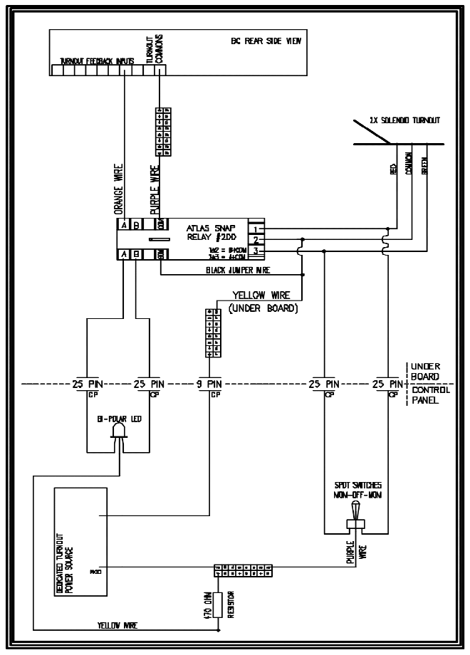
In developing the original KLWZScale I Layout, I wanted to be able to control the layout from a central control panel. This panel needed to indicate the direction of my turnouts and also be able to switch the turnout direction with a minimum amount of effort. In addition I wanted the control panel for the turnouts and the front panel of the RM system to be remote from the layout so I could place the controls on table separate from the layout. First I thought I needed to wire the LED turnout indicator lights separately from the turnout themselves and use two toggle switches. The Marklin Z Scale turnouts are controlled by a solenoid switch, which can only take a momentary pulse of power. (If the power is left on to long the turnout will burnout and cease to work.) The LED lights need a constant source of power to stay lit. Not only did the control panel need to be wired but we can not forget the RM system. The RM needs to receive feedback from the turnouts in order to work. After much research and help from model RR’ers like yourselves and Signal Research I came up with the following wiring system. (will post a better graphic shortly) |
||
The 25 pin and 9 pin connectors are standard computer cables. (Can be purchased from most electronics/computer stores. I used the 15-ft cables) The Atlas snap relays were the key to having just one toggle switch control the turnouts (momentary power), LEDs and feed back to the RM System (constant power). I have the control panel hooked up to a spare Marklin Z Transformer utilizing the grey and yellow plugs. |
||

